Boats? really?
My mother was 8 months pregnant with me, at a lamaze class, waiting for my father who was about to be a no call/no show. He finally showed up with a very valid explanation, the family boat had burned down, sinking into the mud hole we kept it in. Thus began my ill-fated relationship with boats... and by that, I mean that I was not very interested in them, they seemed like a disappointment waiting to happen. The phrase "Break Out Another Thousand" was an acronym I knew for as long as I could remember.
It wasn't until 40 years later, when an instagram comment would open up a world of wonder and excitement. Slackers commented on a video of a little 3D printed Jet Boat made by Cactus Craft Models ripping around a stream: "Fastest purchase I've made in a while, don't even have a working printer" - I replied "I can print this for you" and I was in. As a seasoned builder of FPV quadcopters who also messed around with RC planes quite a bit, this seemed like it would be a fun new adventure.
I was so eager to finally have a "valid" use for my 3D Printers. I've been learning about printers for a few years now. I built a workhorse Ender 3 Pro that has been awesome for TPU, but I never took the time to dial in hard filaments. I recently found a FBM deal on a Bambu A1 that was a little too good to pass up, and that thing opened up everything for printing more materials. The boat seemed like the perfect project to put this to work. AND we could make Slackers happy, everyone wins.
I'm going to share what I learned, but this guide is meant to go along with the USER MANUAL that you got when you PURCHASED the files.
A word of WARNING: This is not a beginner level build. It requires specific micro parts and screws and drivers that you probably don't have on hand... But don't worry, I've compiled a list of build parts and tools needed over HERE. It also requires you to tweak your print settings after loading them, and it takes some patience as some of the parts are designed for different layer heights. I've also made a little chart here of the parts and layer heights HERE. Speaking of printing, let's get started. I'm going to virtually walk through this build with you.
- INTRO -
This is a 1/24 scale RC jet boat, designed by an engineer named Pavel in the Czech Republic. He is kind and accommodating, took suggestions and even included some of our ideas in the upgrade packs. At the time of writing this, this is the only RC jet boat of this scale in existence. Being able to print something like this is very cool and very rewarding but it is challenging, make no mistake. You'll have to spend more than you want to on tiny hardware, you'll get held up for weeks because one part isn't in yet. Here's the best thing we can start with: go sift through the parts list and order whatever is going to take a while now - be kind to your future self and get ahead of the delay this will cause. Let's set some expectations... You don't have to use the servo in the manual, you can make any of them work if they're small enough. you don't have to use the tiny ballcup and ball end pushrod system if you just bend a piece of steel rod a certain way. you don't have to use the same motor and esc, but make sure you pick something that makes sense. and you certainly don't need to build this on 4S unless you need to have insane speed for some reason. 3S is plenty. OK LET'S GO
⋅.˳˳.⋅ॱ˙˙ॱ⋅.˳˳.⋅ॱ˙˙ॱ⋅.˳˳.⋅ॱ˙˙ॱ⋅.˳˳.⋅ॱ˙˙ॱ⋅.˳˳.⋅
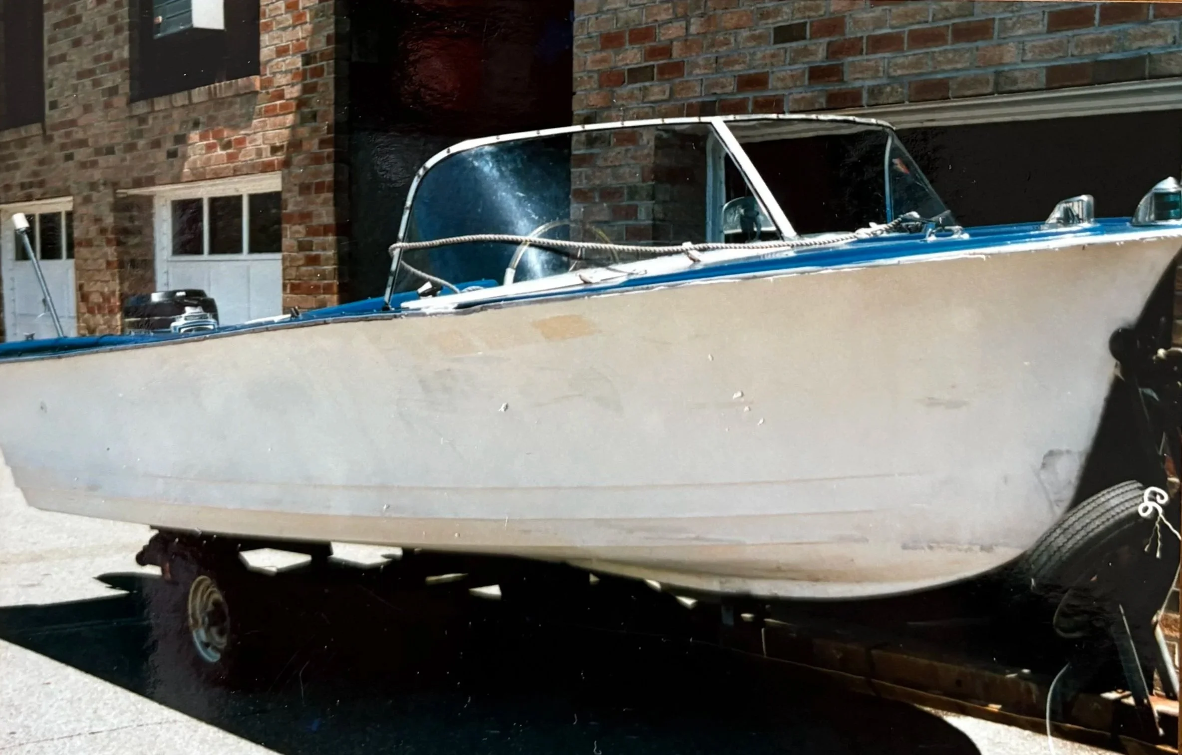
(this guide is for the Wet Biscuit with Upgrade Pack 2)
1. PRINTING IT
did you order those parts yet? trust me, do that before you even start to print.
- SEAMS -
the files come with a default setting of "RANDOM" for the seams. If you print it without changing this setting, it will print with little blobs all over that will make you think you have wet filament. set it to "ALIGNED" or "BACK" for each part you want to print
-LAYER HEIGHT-
the various parts are designed for printing at various heights, from very high detail at 0.08 up to more casual layers at 0.16. I made a little guide to printing over HERE. everything except the window frame will print on a bambu a1 mini.
-MATERIALS-
I'm using PETG-HF and PETG-CF - high flow and carbon fiber - for the everything but the lid which is in TPU. I had to get a hardened steel nozzle to do the CF. I've found that 255 for the PETG-CF and bed at 80 is ideal. Cody, another builder, tried to do multicolor layer printing of the hull and learned that that may not work if the brands of filament are different. Whatever filament you are using, take the time to print a temperature tower and see where you're actually at. you shouldn't need supports for anything. When printing the TPU lid i experienced some lifting of the corners, which was solved by raising the bed temperature and adding a brim.
-DRIVE SHAFT-
The manual prescribes a section of the brass rod filed down, 3mm wide, for the grub screws to grip the shaft. I found an easier way to do this is using a diamond file, cut it to 49mm, dry fit the shaft coupler onto one end, keeping the brass rod end flush with the end of the coupler. Stick the tip of a diamond file into the grub screw hole and spin the file scuffing the surface of the brass rod. do this above and below, remove the coupler and file down the spot where the grub screws sit. insert the coupler back onto the shaft but don't install the grub screws yet... dry fit some o rings and bearings into the hull and push the coupler and rod into place from inside the boat. slide the impeller WASHER onto the shaft before you slide the impeller into place. the impeller should be flush with the rear surface of the boat and spin freely. if it gets hung up on the sides of the jet port, sand down the prop sides (but not too much!) remove the coupler from the front side of the drive shaft, and pull the shaft out from the rear of the boat keeping the impeller in place. do the same trick with the file for the impeller grub screw holes. once you've filed this side down as well, insert the grub screws with some loctite into the impeller, and remove one of the bearings. fill the tube where the driveshaft goes with marine grease. put it all back together, wipe the grease off and tighten the grub screws. a third bearing goes inside the nozzle to receive the rest of the drive shaft sticking out past the impeller. Don't install the nozzle yet, we'll work on the pushrod next.
-JET PUSHROD-
if using the original method with the orlandoo balls and printed cups, be sure servo is mounted directly in line with the hole and the bracket where it attaches to the jet. the ballcup method requires precise straight rod path. Cody came up with he brilliant idea to apply model airplane tech by bending a steel rod in a Z form for the servo horn and Jet bracket. I took a piece of 1mm steel, used needle nose to bend a Z in the one side while leaving the other end straight. insert the Z bend into the servo horn, and insert the straight end of the pushrod into the hole in the hull: from the inside, out towards the back. screw the servo into the servo mount. using 10mm bolts, a thin washer on top, servo mount and then tall washer below, loosely assemble the servo mount/bolts/washers and hold the boat upside down to keep the washers in place while fitting the parts inside. if the servo arm is putting and angle pressure on the z rod while in place, a bit of bend can be applied with pliers to relieve tension. on the rear of the hull, install two or three o rings and some grease into the pushrod seal part and fasten it to the hull using 6mm bolts.
Install a bearing into the nozzle and install the main nozzle, attaching the duct with 6mm bolts top and bottom, and the bracket will be attached to the duct with 4mmm bolts. install the bracket and tighten the duct down to be straight, mark on the steel rod where the hole is on the bracket, and bend another Z into it so that it lands in the straight position. it's crucial to measure this distance after plugging in your servo to your receiver and powering on so that it settles in the middle if you do not want to remove the servo horn to do this later.
-GLUE IT UP-
The part that the lid sits in needs to be glued to the hull, and i did this wrong the first time using superglue sparingly. It works but you need to use enough. Epoxy is probably the way to go when glueing the rectangle frame into the hull. Printing the lid may lead to small strings across one corner of the inside of the seal, trim it out with cuticle cutters or an xacto or something. test for leaks by holding it under water and pushing on the lid to see where the bubbles come out, that's how i found my leak.
-MOTOR MOUNT-
Install the coupler to the top of the motor with 8mm screws, and fit the motor mount parts together as per the images in the manual. a washer and a 10mm bolt can be loosely fit as the motor is shifted back and forth to create a loose fit with the drive shaft coupler. install the ESC and RX tray on the left side (opposite the servo) and install the battery mount ahead of the motor. experiment with weight and how it floats. Set the ESC by connecting to the rx with the throttle at full. there will be beeps, move the throttle back and forth a few times and leave it at minimum, the esc will beep some more. reboot and it should be calibrated. for creatively programming a typical drone ELRS RX for 2 CH PWM output, click HERE